It’s important to understand the basics of wireless range and network repeaters. This guide, written by the by our engineering team, is full of useful tips to help ensure that your wireless system is as reliable and powerful as possible.
We will try to explain the factors that affect wireless range, and also present some tips on how to maximize wireless range in your wireless network.
Do Not Bring In Da Noise
Surprisingly, probably the most important factor that determines the range between a device and your receiver has little to do with the device or the receiver- it’s actually the amount of electromagnetic “noise” that is present in the environment.
Because of the electromagnetic noise from various devices, your devices are constantly fighting to hear each other.
Here are a few things that affect wireless noise:
- Wi-Fi access points (both yours and your neighbors’)
- Mobile phones
- Microwave ovens
- Baby monitors
- Fluorescent lights
- Wireless game controllers
- Consumer devices that form their own private Wi-Fi networks (e.g., iPads, Sonos)
- Cheap (or defective) electronics that saturate the airwaves with electromagnetic radiation
Since most security products work in the 868Mhz frequency space, they are most effected by similar security technologies and 4G/LTE (Fourth Generation / Long Term Evolution) as used by Vodafone, O², Three and EE.
ZigBee works in the 2.4 GHz frequency space, it is most affected by 2.4 GHz Wi-Fi networks and microwave ovens.
The 2.4 GHz frequency used by Wi-Fi and ZigBee actually comprise a range of channels, just like broadcast TV. If you can move your Wi-Fi channel to be farther away from your ZigBee channel, it will go a long way toward reducing the noise.
It’s tempting to put your receiver right next to your control panel, but this is probably the worst possible place for it. The farther away you can keep wireless devices, the less the noise from one will interfere with the other.
Repeaters
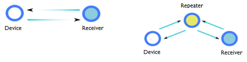
A repeater can act as a relay point, so that a device that is too far from the receiver can talk to a repeater that is closer, and the repeater relays the messages back and forth to the receiver.
The diagrams below show how a repeater can help. On the left, a device that is far from the receiver is not communicating reliably. But if a repeater is placed between the device and the receiver, the device talks to the repeater, the repeater talks to the receiver and reliability is greatly improve
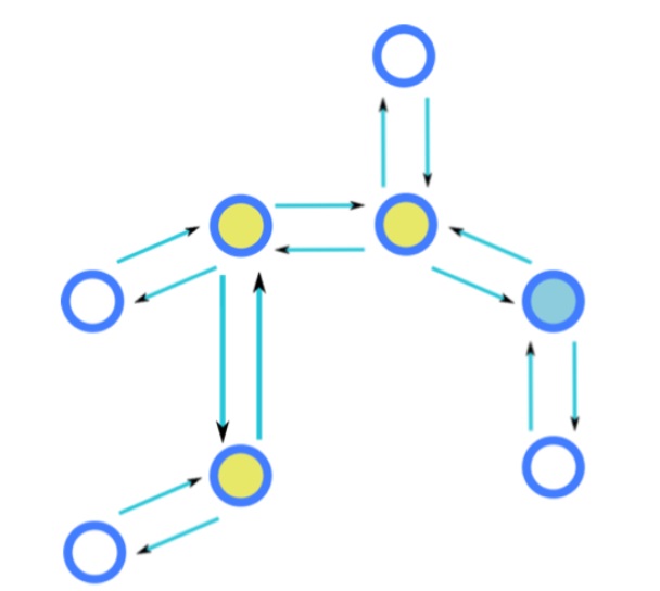
Repeaters can talk to other repeaters, and a very robust “mesh network”, as used by Inovonics can be formed, as in this diagram.
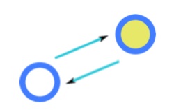
A non-repeater device (i.e., a battery-powered device) always has to have a receiver to talk to, either the receiver itself or a repeater. When the device first joins the network, or is forced to find a new receiver, it will obviously pick the receiver that gives it the strongest signal. However, once a device picks a receiver, it will hold on to it until it absolutely cannot talk to it any more, even if a different receiver is introduced into the network that would be a better choice!
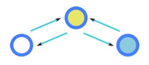
The diagram below illustrates how this can happen. On the left a device is parented to the receiver, the communication is poor and many messages are lost, but the device and the receiver still communicate well enough for the device to consider the receiver its parent. You would think that introducing a repeater half-way between the device and the receiver (shown on the right) would magically fix the problem, but because the device can still occasionally talk to the receiver, it does not re-parent to the repeater. This is not true for Inovonics repeaters in “Broadcast” mode, as all signals, weak or strong, are received and re-transmitted.

In about 5-10 minutes, the device will give up trying to talk to its missing parent and find a new one–the repeater we added half-way between the device and the receiver! A major downside of this type of loss is excessive battery usage, a common problem for battery bi-directional devices.
Finally, when you turn the receiver back on the repeater will establish a link with the receiver, and all will be well.
Unfortunately, this process does not work for the Z-Wave network, since Z-Wave devices do not automatically look for new parents.
Obstacles and Detours
A wireless signal ideally follows a straight path from source to destination. When companies try to impress you with their product’s wireless range, they will undoubtedly quote this line-of-sight straight-path distance (measured on an open space in the Nevada desert, away from anything that emits noise, away from any radio stations, with the devices pointed directly at each other, etc.) as the best-possible-case range.
The reality is that in a typical home or business, devices often do not have a clear line-of-sight path to the receiver or their parent. Wireless signals have to travel through mostly-transparent (well… electromagnetically transparent) floors and walls, and reflect off mostly-opaque surfaces such as concrete and metal, to find their way from source to destination.
Even mostly transparent materials such as wood and drywall (Plasterboard) still introduce some power loss in the wireless signal, leading to potential range issues if many floors and walls have to be crossed.
Here are some tips for thinking about wireless range in terms of obstacles and detours:
- Visualize the paths
Try to visualize the paths that wireless signals take from devices to their closest parent. If you have the flexibility, arrange devices and repeaters to have line-of-sight between each other.
- Watch out for barriers
If there is an obstacle between a device and its parent, especially if they are already somewhat far from each other, consider repositioning so that the wireless signal does not have to travel through the obstacle. Obstacles include: – Metal objects or sheets (e.g. Appliances, Machinery)
– Cinder block
– concrete walls
– Bodies of water (e.g. aquaria, water storage)
- Use repeaters
- Don’t place your receiver or repeater within or next to a metal control panel or power supply.
Metal surfaces interact with the receiver’s antenna radiation pattern and reduce its effective power. Therefore, you should ideally keep the receiver a couple of feet away from large pieces of metal. If this can’t be avoided, you know what to do… use a repeater!
Angles, Orientations, and Reflections
While we’re talking about wireless antennas, note that an antenna’s angle/orientation (relative to the device it’s communicating with) can have a pretty big effect on how well this communication works.
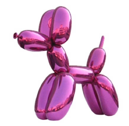
First, let’s look at the ideal antenna, one which emits electromagnetic radiation in all directions with equal power.

Yup, it’s a balloon. Pretend the balloon is inflating and think of the surface of the balloon as representing an electromagnetic wave that is propagating away from the center (the transmitter) equally in all directions. This is good because it means we can reach our devices in all directions, plus bounce the signal off all concrete walls.
Now here is the worst possible antenna.
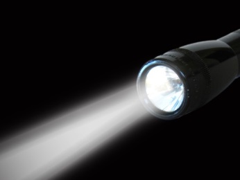
A flashlight concentrates its light in a beam in a single direction. If an antenna behaved like that, any device not in the path of its beam would appear to be completely out of range, even if very close by. There are some situations in which a “flashlight antenna” (or what we actually call a highly directional antenna) is a good thing, for example satellite uplink/downlink antennas, because we really only want to talk to a single faraway device and we know where it is. But this type of antenna pattern is not good for wide area coverage.
Finally, here is a more realistic antenna because, as is so often the case in the real world, the ideal antenna cannot physically be built and exists only in our minds.
There are some angles at which the antenna radiates well, others at which it has “blind spots”, and overall it’s a very complicated three-dimensional radiation pattern.
Normally you don’t have to worry about the antenna pattern, but you may just be unlucky and have a device and the receiver (or its parent) aligned in such a way that they are in each other’s antenna blind spots. If you have a device that always seems to be struggling to perform well, and physical distance or obstacles are not major factors, consider rotating it or shifting its position just a little bit, just in case the issue is one of alignment.
Remember, too, that we count on reflections off walls, doors, and other objects to compensate for the blind spots in the antenna pattern, and for not having true line-of-sight between devices in the network and the receiver. It is helpful, therefore, to make sure that the receiver has its orientation pointed towards the center of the coverage area, where reflections can happen, rather than away from the area where the signal will go out of the area of coverage.
There are many, many factors that affect sensor range, including ones we haven’t even mentioned in this article, (like the air temperature, humidity–and yes–even sunspot activity). This is why it is so difficult to state a specific range for any wireless product. Our guide has been limited to factors you can actually control to some degree. At the end of the day, the more you understand about what influences your range, the more likely you are to extend the range of what your location is capable of.
Inovonics’ EchoStream technology is by far the most powerful wireless sensor network available for the commercial building market. Based on 25mW frequency-hopping, spread-spectrum technology, their wireless network sends redundant messages across multiple channels to avoid interference obstacles.
The intelligent repeaters, which provide the backbone of the network, can accommodate virtually any size application, and the combination of short on-air time and sophisticated power management allows extended battery life.
Due to its low latency and high reliability, Inovonics technology is an ideal solution for life safety and security applications. Other applications that don’t have the latency demands of life safety and security are also easily integrated.